

API 660 is one of the key standards for shell-and-tube heat exchangers used in petroleum, petrochemical, and natural gas service. It helps establish consistent requirements for equipment that often operates under demanding pressure, temperature, corrosion, fouling, and thermal-cycling conditions.
Published by the American Petroleum Institute, API 660 covers key areas including design, materials, fabrication, inspection, and testing.
This guide explains what API 660 requirements cover and how the standard works with ASME, TEMA, and ISO 16812 in real heat exchanger projects.
CONTENT:
- What Is API 660?
- What Does API 660 Require for Shell-and-Tube Heat Exchangers?
- How Do API 660, ASME, and TEMA Work Together?
- FAQ About API 660
- Conclusion
What Is API 660?
API 660 is an industry standard published by the American Petroleum Institute for shell-and-tube heat exchangers used in petroleum, petrochemical, and natural gas processing. It establishes a common technical basis for how these exchangers should be designed, manufactured, inspected, tested, and prepared for delivery.
The standard applies to common exchanger services such as heaters, coolers, condensers, and reboilers. It does not apply to vacuum-operated steam surface condensers or feed-water heaters.
| API 660 at a Glance | |
|---|---|
| Scope | Shell-and-tube heat exchangers for petroleum, petrochemical, and natural gas service |
| Equipment | Shell-and-tube heat exchangers |
| Main industries | Petroleum, petrochemical, natural gas |
| Typical services | Heaters, coolers, condensers, reboilers |
| Main coverage | Mechanical design, materials, fabrication, inspection, testing, shipment preparation |
Why is this important? In refinery and petrochemical service, a heat exchanger has to manage more than pressure alone. Temperature differences, thermal expansion, corrosion, fouling, vibration, erosion, and cyclic operation can all affect long-term reliability.
Specifying only the required heat duty is rarely enough. Exchanger configuration, materials, mechanical details, fabrication controls, inspection, and project requirements need to be considered together. API Standard 660 provides a consistent framework for doing that.
Heat Exchanger Overview
How Does API 660 Fit into the Broader Heat Exchanger Design Framework?
See how shell-and-tube heat exchangers fit into the broader heat exchanger family, how different exchanger types compare, and which process conditions guide equipment selection.
Explore Heat Exchangers →What Does API 660 Require for Shell-and-Tube Heat Exchangers?
API 660 requirements are not limited to a single design calculation. They follow the exchanger from mechanical design and material selection through fabrication, inspection, testing, and preparation for shipment.
For a typical project, the requirements can be understood in five connected areas:
| Requirement Area | What It Covers |
|---|---|
| Mechanical Design | Pressure and temperature conditions, tubes, tubesheets, baffles, thermal expansion, nozzle loads, vibration and other mechanical details |
| Materials | Material selection, corrosion resistance and corrosion allowance |
| Fabrication | Welding, tube-to-tubesheet joints, dimensional tolerances and PWHT where required |
| Inspection & Testing | NDE, dimensional inspection, pressure testing and leak testing |
| Documentation | Design calculations, drawings, material records, welding/NDT records and final project documents |
These requirements are closely connected. A change in operating temperature or material, for example, can affect mechanical design, welding procedures, heat treatment and inspection requirements at the same time.
The following sections look at each requirement area in more detail.
Mechanical Design Requirements
Mechanical design is the first major requirement area in API 660. Some values come from the project conditions, while others are defined by the standard as minimum limits or allowable values.
| Item | Specific API 660 Requirement* |
|---|---|
| Minimum tube outside diameter | 19.05 mm (3/4 in.), unless otherwise specified or approved |
| Minimum tube wall thickness – carbon / low-alloy steel | 2.11 mm (0.083 in.) |
| Minimum tube wall thickness – copper alloys | 1.47 mm (0.058 in.) |
| Minimum tube wall thickness – high-alloy steel / other nonferrous materials | 1.47 mm (0.058 in.) |
| Minimum tube wall thickness – titanium | 1.07 mm (0.042 in.) |
| U-bend radius | Normally at least 1.5 × tube OD; certain alloys require 2.0 × tube OD |
| Slip-on flange restriction | Not permitted above 2100 kPa(g) / 300 psig, above 400°C / 750°F, or under certain corrosive / cyclic services |
| Chemical-cleaning connection | Minimum DN 50 (NPS 2) when specified |
| Nozzle loads | Allowable forces and moments are specified by nozzle size and flange rating |
*Values are based on API 660 Ninth Edition requirements and should be checked against the project-specified edition.
The API 660 nozzle loads table is a good example of how specific the standard can be: it provides defined allowable forces and moments instead of leaving piping loads entirely to engineering judgment.
Other items, such as design pressure, design temperature, and thermal expansion, depend on the actual service conditions. These design choices also affect material selection, which is covered next.
Material Requirements
Material selection follows the actual process conditions. Pressure, temperature, fluid chemistry, corrosion mechanisms, and expected service life all influence the final choice.
API 660 also sets several specific material requirements:
| Material Area | Specific API 660 Requirement* |
|---|---|
| Alloy lining | Must be weld overlay, integrally clad, or explosion-bonded. Loose liners or sleeves require purchaser approval. |
| Weld overlay | Specified chemical composition must be maintained to a depth of at least 1.5 mm (1/16 in.) from the finished surface. |
| Tubesheet cladding – tube side | Minimum 10 mm (3/8 in.) for expanded-only tube joints and 5 mm (3/16 in.) for welded tube joints. |
| Tubesheet cladding – shell side | Minimum 10 mm (3/8 in.). |
| Carbon steel in sour / wet H₂S service | Normally supplied in the normalized condition, unless otherwise approved by the purchaser. |
| Sour-service material records | Pressure-retaining components require a Certified Material Test Report (CMTR) with chemistry needed to determine carbon equivalent. |
| Gaskets | Asbestos is prohibited. Metallic gasket materials must have corrosion resistance at least equal to the gasket-contact surface. |
| Compressed-sheet gaskets | Not permitted for hydrocarbon, steam, hydrogen, sour, or wet-H₂S service. |
*Values are based on API 660 Ninth Edition requirements and should be verified against the edition specified for the project.
For sour or high-temperature hydrogen service, additional material requirements may also come from NACE MR0103 / ISO 17945 or API RP 941.
Corrosion allowance is project-specific. A typical value may be around 1.5–3 mm, but the final requirement should follow the actual corrosion assessment and purchaser specification.
Once the material requirements are confirmed, the next step is controlling how those materials are welded, machined, and assembled during fabrication.
Fabrication Requirements
Fabrication turns the approved design into the finished exchanger. Key controls include welding procedures, tube-to-tubesheet joints, machining tolerances, and PWHT where required. WPS, PQR, qualified welders, and controlled tube joining are therefore part of the fabrication basis.
API 660 also gives specific fabrication limits:
| Fabrication Item | API 660 Requirement* |
|---|---|
| Tube holes for selected alloy tubes | Austenitic stainless steel, duplex, titanium, cupronickel, and nickel-alloy tubes require TEMA Special Close Fit tube holes |
| Roller-expanded joints | Maximum tube-wall reduction: 8% for carbon/low-alloy steel, 6% for stainless/high-alloy steel, and 5% for titanium/work-hardening nonferrous materials |
| Welded + expanded joints | Tube expansion should begin at least 6 mm (1/4 in.) from the weld |
| Expansion near shell-side face | Expansion should stop at least 3 mm (1/8 in.) from the shell-side tubesheet face |
| Weld hardness | Maximum 225 HBW for carbon steel and Cr steel up to 3% Cr; 241 HBW for 5–17% Cr steel |
| Stacked exchanger flange alignment | Mating nozzle flanges: out-of-parallel ≤ 0.8 mm (1/32 in.); separation after gasket installation ≤ 3 mm (1/8 in.) |
*Values are based on API 660 Ninth Edition requirements and should be checked against the edition specified for the project.
Tube-to-tubesheet joints may use expansion, strength welding, seal welding, or a combination of welding and expansion. The method must achieve a leak-tight joint without excessive tube-wall thinning or damage.
PWHT is not defined by one universal API 660 temperature or thickness limit. Its need depends on the material, thickness, service, welding configuration, and applicable pressure design code. Where PWHT is required, subsequent hardness testing and inspection must account for the heat-treated condition.
These fabrication controls are then verified through inspection and testing.
Inspection and Testing Requirements
After fabrication, inspection and testing are used to verify weld quality, joint integrity, dimensional accuracy, and pressure containment.
| Inspection / Test | Specific API 660 Requirement |
|---|---|
| Welded-and-expanded tube-to-tubesheet joints | Pneumatic leak test at 50–100 kPa (7.5–15 psi) before final tube expansion |
| Shell and tube sides | Independent hydrostatic tests are required, except for differential-pressure designs |
| Hydrostatic test duration | Test pressure maintained for at least 1 hour |
| Test water | Potable water |
| Austenitic stainless steel | Chloride content in test water ≤ 50 mg/kg (50 ppm) |
| Helium leak testing | Performed after final expansion when specified by the purchaser |
| Nonmagnetic welds | Liquid penetrant testing is used where magnetic-particle examination is not applicable |
| After PWHT | Required weld examinations and final visual inspection are carried out after heat treatment where applicable |
*Values are based on API 660 Ninth Edition requirements and should be checked against the edition specified for the project.
API 660 does not use one fixed hydrostatic test pressure for every exchanger. The test pressure depends on the applicable pressure design code, material allowable stresses, and project conditions.
Radiographic testing (RT), liquid penetrant testing (PT), dimensional inspection, hydrostatic testing, and leak testing may therefore be combined according to the exchanger design and specified inspection scope.
These records are then included in the final documentation package.
Documentation Requirements
API 660 also requires the exchanger to be supported by a complete technical record. These documents allow the purchaser to verify design, materials, fabrication, inspection, and final as-built condition.
| Document Type | Typical Contents |
|---|---|
| Design documents | Mechanical calculations, stress calculations, thermal rating data |
| Drawings | General arrangement, fabrication drawings, nozzle schedules, component details |
| Material records | Material Test Certificates, mill certificates, heat-number traceability |
| Welding records | WPS, PQR, welder qualifications |
| Inspection records | RT, PT and other NDT reports, dimensional inspection records |
| Test records | Hydrostatic and leak-test reports |
| Final documentation | As-built drawings and approved vendor data |
These records remain useful well after delivery. They support installation, commissioning, future inspection, maintenance, revamp, and replacement work.
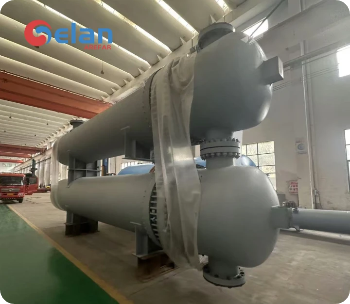
The heat exchanger specification and API 660 datasheet bring together the process conditions, design basis, materials, exchanger configuration, and purchaser requirements used by the manufacturer.
How Do API 660, ASME, and TEMA Work Together?
A shell-and-tube heat exchanger project may reference all three, but they serve different purposes:
- ASME Section VIII: Focuses on pressure-vessel safety, including pressure-boundary design, allowable stress, welding, examination, and pressure testing.
- TEMA: Defines how shell-and-tube heat exchangers are configured and mechanically constructed, including exchanger types, tubesheets, baffles, bundles, clearances, and fabrication practices.
- API 660: Adds more specific requirements for shell-and-tube exchangers used in refinery, petrochemical, and natural-gas service. In many areas, it places additional limits or requirements beyond the basic TEMA provisions.
For an ASME heat exchanger design, Section VIII establishes the pressure-boundary basis, while TEMA and API 660 address exchanger-specific construction and service requirements.
A typical project may therefore specify:
ASME Section VIII + TEMA Class R + API 660 + purchaser specification
Because ASME mainly governs the pressure boundary, the most direct requirement-by-requirement comparison is between API 660 and TEMA.
API 660 vs TEMA: Key Requirement Differences
| Subject | API 660 Requirement | TEMA Requirement |
|---|---|---|
| Tubesheet cladding thickness | Minimum 10 mm for expanded tube-to-tubesheet joints; 5 mm for welded joints | Class R/B: 7.8 mm expanded, 3.2 mm welded; Class C: 4.8 mm expanded, 3.2 mm welded |
| Sliding saddle anchor-bolt slot | Slot width = anchor-bolt diameter + 8 mm (5/16 in.); slot length also includes longitudinal movement allowance | No specific numerical slot dimensions |
| Floating-head exchanger types | TEMA Type P and W exchangers are not allowed | Type P is allowed; Type W is allowed for limited services |
| Backing-device corrosion allowance | Shell-side corrosion allowance is included on the back side of the floating-head backing device | No corrosion allowance required |
| Minimum tube OD | 19.05 mm (3/4 in.) | Smaller tubes, down to about 6.4 mm, may be permitted |
| Minimum tube thickness | Minimum thickness defined according to tube material | No equivalent material-specific minimum thickness requirement |
| Tubesheet extension | Full-diameter stationary tubesheet required for removable bundles with bonnet-type front heads | No specific tubesheet-extension requirement |
| Baffle thickness | Carbon/low-alloy steel baffles and support plates must include the specified shell-side corrosion allowance | Thickness based mainly on shell diameter and plate spacing; corrosion allowance not generally required |
| Impingement plate thickness | Minimum 6 mm (1/4 in.) | No specific minimum thickness |
| Perforated impingement plate | Perforated impingement-plate baffles are not permitted | Perforated distribution devices may be used |
| Bypass sealing devices | Specific provisions for seal strips, tie rods, dummy tubes, and other bypass-control devices | No equivalent numerical requirement |
| Seal-strip thickness | At least the transverse-baffle thickness or 6 mm (1/4 in.), whichever is less | No specific thickness requirement |
| Stud washers | Hardened washers required for studs 38 mm (1½ in.) and larger; minimum washer thickness 6 mm (1/4 in.) | No equivalent requirement |
| Flange allowable stress | Short-time tensile-strength-based allowable stress is not permitted for girth flanges, gasketed tubesheets, and gasketed flat covers | No equivalent restriction |
| Thin-wall expansion joints | Detailed requirements covering service, cycle life, liner design, and related conditions | Not specifically covered |
| Gasket construction | Requirements specified for welded/non-welded, serrated, jacketed, corrugated, and spiral-wound gaskets | No equivalent detailed requirement |
| Integrally finned copper-alloy tubes | Required in the annealed-temper condition in accordance with ASTM B359/B359M | No specific requirement |
| Shell ovality | For removable bundles, ovality checked using a metal template made from at least two disks and spaced at least 300 mm apart | Fabricated shell ID limited by circumferential measurements; no metal-template requirement |
| Pass-partition plate weld | First 50 mm from gasket face must be full-penetration welded where partition plate is welded on both sides | No equivalent full-penetration requirement |
| PWHT – channel | Additional PWHT requirements apply to certain CS/LAS channels, including multi-pass or high nozzle-to-ID ratio designs | No equivalent specific requirement |
| PWHT – floating head | CS/LAS floating heads fabricated from dish-and-ring construction require PWHT | No equivalent specific requirement |
| Stacked exchanger tolerances | Mating nozzle-flange tolerances are more restrictive | Uses standard TEMA Figure F-1/F-2 tolerances |
| Tube holes | “Special Close Fit” holes required for austenitic stainless steel, duplex, titanium, cupronickel, and nickel-alloy tubes | No equivalent material-based requirement for standard vs special close fit |
| Maximum tube-wall reduction | Specific maximum roller-expansion reduction defined for different tube materials | No equivalent material-specific limit |
| Expansion length inside tubesheet | For welded-and-expanded joints, expansion begins 6 mm from the weld and stops 3 mm from the shell-side face | Expansion generally extends through the tubesheet with a smaller end clearance |
| Pneumatic test for welded tube joints | Additional pneumatic test required before final expansion of welded-and-expanded tube-to-tubesheet joints | No equivalent specific requirement |
*The detailed values above are based on the API 660/TEMA comparison data provided for this article. Exact requirements should always be checked against the editions and purchaser specifications specified for the project.
This comparison shows why API 660 vs TEMA is not simply a question of choosing one standard. TEMA provides the basic exchanger construction framework, while API 660 adds more prescriptive requirements in areas where refinery service demands tighter control of corrosion allowance, tube construction, flow distribution, fabrication, and inspection.
FAQ About API 660
Is API 660 mandatory for all shell-and-tube heat exchangers?
No. API 660 applies when it is specified by the purchaser, EPC contractor, project specification, or applicable regulatory requirements. It is most commonly used for petroleum, petrochemical, and natural-gas projects.
Is API 660 only for shell-and-tube heat exchangers?
Yes. API 660 specifically covers shell-and-tube heat exchangers. These units may serve as heaters, coolers, condensers, or reboilers, but they remain shell-and-tube exchangers.
How does ISO 16812 relate to API 660?
ISO 16812:2019 covers the same general type of equipment and explicitly supplements API 660 Ninth Edition, with specified exceptions and additions. ISO confirmed the 2019 edition again in 2024, so it remains current.
Does API 660 replace ASME or TEMA?
No. ASME provides the pressure-vessel design code, TEMA provides the shell-and-tube exchanger construction framework, and API 660 adds requirements for refinery and related process services. Projects often reference all three.
Conclusion
API 660 sets key requirements for shell-and-tube heat exchangers used in demanding refinery, petrochemical, and natural-gas service. It covers mechanical design, materials, fabrication, inspection, testing, and documentation.
In practice, API 660 is often used together with ASME, TEMA, and project specifications. For API 660 exchanger projects, Gelan can support design clarification, fabrication, testing, and documentation.