

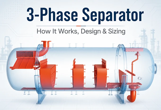
In oil and gas projects, poor separation at the front end can quickly create problems downstream. From Gelan’s project experience, a properly designed 3-phase separator helps stabilize gas, oil or condensate, and produced water before these streams enter compression, storage, or water-treatment systems.
This article explains what a 3-phase separator is, how it works, and the key design, sizing, safety, and application considerations behind reliable separation.
CONTENT:
- What Is a 3-Phase Separator?
- Why Are 3-Phase Separators Important in Oil & Gas?
- How 3-Phase Separation Works
- 3-Phase Separator Design Parameters and Standards
- 3-Phase Separator Safety and Operating Risks
- Performance Benefits of Gelan's 3-Phase Separators
- FAQ About 3-Phase Separators
- Conclusion
What Is a 3-Phase Separator?
A 3-phase separator is a pressure vessel used to separate a mixed stream into gas, oil or condensate, and water. This type of oil and gas separator is commonly installed near the front of the surface processing system, before the separated streams move to downstream treatment, storage, or disposal.
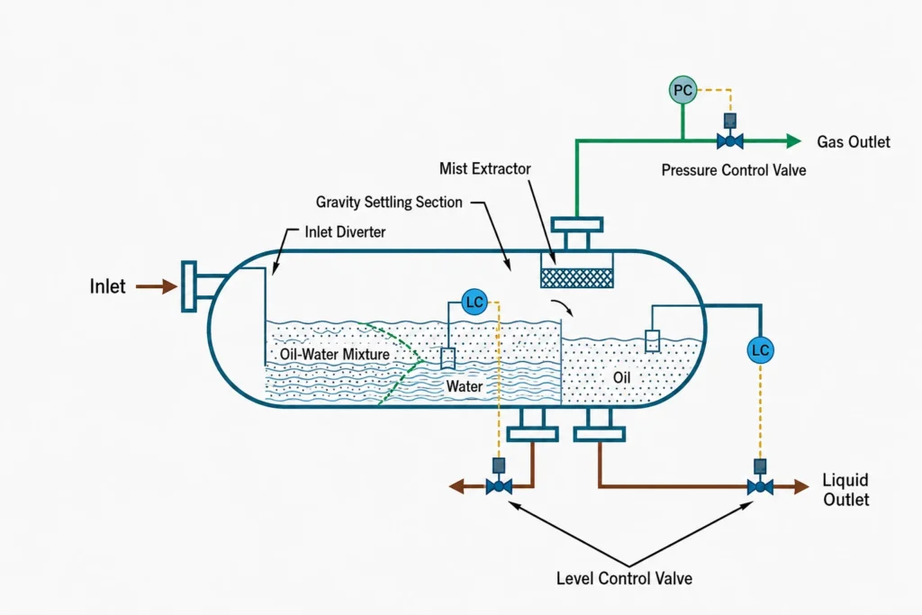
The separation mainly relies on density differences. Gas rises to the top, oil forms the middle layer, and water settles at the bottom. Internal components such as inlet diverters, weirs, and mist extractors help stabilize the flow and improve separation.
Why Are 3-Phase Separators Important in Oil & Gas?
A three-phase production separator is often one of the first major separation units in an oil and gas production system. Its performance directly affects product quality, downstream equipment, and overall operating stability.
- Operational Efficiency: Stable separation reduces liquid carryover and helps compressors, heat exchangers, pipelines, and storage systems operate more reliably.
- Product Quality: Effective oil-water separation lowers water carryover in the oil or condensate stream and helps maintain downstream product specifications.
- Process Safety: Controlled pressure, liquid level, and oil-water interface reduce the risk of overpressure, unstable flow, and phase carryover.
- Produced Water Management: Separating water early reduces the load on downstream water-treatment systems before disposal or reinjection.
- Operating Flexibility: Horizontal separators with weir plates are well suited to higher liquid loads and changing flow conditions because they provide more settling space and better oil-water interface control.
In practice, these production separators should not be treated as isolated vessels. When gas, oil, and water are separated more steadily at the front end, the entire production system becomes easier to control and more reliable downstream.
How 3-Phase Separation Works
The working principle of 3-phase separation is simple: give gas, oil, and water enough time and calm space to separate naturally. Gas is the lightest, oil stays above the water, and water settles at the bottom. Inside the separator, several components help this process happen faster and more steadily.
1. The incoming flow slows down.
The mixed well stream enters the vessel at high velocity. An inlet diverter reduces its momentum and spreads the flow more evenly. This creates a calmer separation zone and reduces unnecessary turbulence.
2. Gas moves to the top.
Once the flow slows, gas separates from the liquid and rises into the upper part of the vessel. A mist extractor removes small liquid droplets carried with the gas before it leaves through the gas outlet.
3. Oil and water form separate layers.
The remaining liquid stays in the vessel long enough for gravity to work. Heavier water settles at the bottom, while lighter oil or condensate forms a layer above it. Weirs, baffles, or coalescing internals can help small droplets combine and separate more quickly.
4. The three phases leave separately.
Gas leaves from the top, oil through the oil outlet, and produced water through the water outlet. Level and interface controls keep the oil-water boundary in the correct range so that oil does not leave with the water and water does not carry over with the oil.
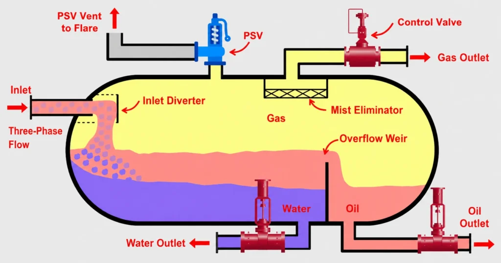
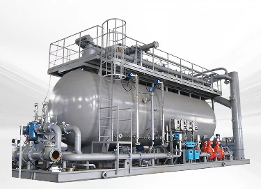
For projects with changing flow rates or more difficult oil-water separation, the internal arrangement becomes especially important. Gelan designs and manufactures custom 3-phase separators with suitable inlet devices, weirs, mist removal, level control, and other internals based on the actual process conditions, helping clients achieve more stable separation before the fluids move downstream.
3-Phase Separator Design Parameters and Standards
A reliable 3-phase separator design depends on more than vessel size. The internal arrangement must support gas disengagement, oil-water separation, stable level control, and safe operation under changing flow conditions. This is why separator design usually starts with both the vessel layout and the key components inside it.
Key Design Components
A typical 3-phase separator may include:
- Inlet Diverter: Reduces the momentum of the incoming stream and helps start the first gas-liquid separation.
- Mist Extractor: Removes fine liquid droplets from the gas before it leaves the vessel.
- Weir Plate: Helps separate the oil and water sections and maintain a stable oil-water interface.
- Baffles or Coalescing Internals: Help small droplets combine into larger ones, making gravity separation faster and more effective.
- Level and Interface Controls: Keep the liquid level and oil-water interface within the required operating range.
- Pressure Relief Devices: Protect the vessel from overpressure.
- Manways and Inspection Openings: Provide access for inspection, cleaning, and maintenance.
The exact internal arrangement depends on the process stream. A separator handling high water cut, changing liquid loads, or difficult oil-water separation may need a different combination of internals than a unit operating under more stable conditions.
Design Parameters and Sizing Calculations
Before 3-phase separator sizing begins, the design team first needs a clear set of process data. The most important inputs normally include:
- Gas flow rate
- Oil or condensate flow rate
- Water flow rate
- Operating pressure and temperature
- Gas, oil, and water densities
- Oil viscosity
- Expected droplet size or separation target
- Required liquid retention time
- Slug or surge volume
- Required outlet quality, such as allowable water in oil or liquid carryover in gas
These values define how much gas space, liquid volume, and settling distance the separator needs. Once the process data are confirmed, the sizing can be checked step by step.
Step 1: Convert Production Rates to Mass Flow
The production rates of gas, condensate, and water are first converted into mass flow rates:
ṁ = Q × ρ
where:
- ṁ = mass flow rate
- Q = volumetric flow rate
- ρ = fluid density
This conversion provides a consistent basis for the following separator calculations.
Step 2: Convert to Consistent Volumetric Flow Units
All streams are then converted into consistent volumetric flow units, such as ft³/s, so the gas and liquid flow rates can be compared and used on the same calculation basis.
For field-unit calculations:
- 1 bbl = 5.615 ft³
- 1 day = 86,400 s
Step 3: Estimate the Allowable Gas Velocity
The gas-handling capacity is checked using the Souders–Brown correlation:
Uₜ = K × √[(ρₗ − ρᵥ) / ρᵥ]
where:
- Uₜ = maximum allowable vapor velocity
- K = empirical design factor
- ρₗ = liquid density
- ρᵥ = vapor density
In Gelan’s reference calculation for a horizontal separator, a K value of 0.35–0.50 ft/s is used. This check keeps the gas velocity low enough for entrained liquid droplets to settle out before the gas leaves the separator.
Step 4: Determine Liquid Hold-Up and Surge Volume
The liquid hold-up volume is calculated from the liquid flow rate and required retention time:
Vₕ = Q × tᵣ
where:
- Vₕ = liquid hold-up volume
- Q = liquid flow rate
- tᵣ = retention time
Additional surge volume is then provided to accommodate temporary flow fluctuations. In Gelan’s reference design, this allowance is typically 10–20% of the hold-up volume.
Step 5: Check Actual Vapor Velocity
The actual vapor velocity inside the separator is compared with the allowable vapor velocity:
Uᵥₐ < Uₜ
This confirms that the gas velocity remains low enough to reduce excessive liquid carryover into the gas outlet.
Step 6: Estimate the Minimum Separation Length
The minimum length required for vapor-liquid separation is estimated as:
Lmin = Uᵥₐ × φ
where:
- Uᵥₐ = actual vapor velocity
- φ = liquid-droplet dropout time
This provides enough travel distance for entrained liquid droplets to settle before the gas reaches the outlet.
Step 7: Select Separator Diameter and Check L/D
The vessel diameter is selected based on the required gas-handling and liquid capacity. The overall vessel geometry is then checked using the length-to-diameter ratio.
In Gelan’s reference design:
L / D = 3.5
This ratio is used as a design check for the selected horizontal separator. The final L/D ratio can still be adjusted according to actual process conditions, internal arrangement, fabrication requirements, and project specifications.
Design Codes and Standards
The design of a 3-phase separator usually combines process-design references with pressure-vessel codes. The main standards and references include:
- API RP 12J: Provides recommended practices for the process design of oil and gas separators and scrubbers, including separator configuration, sizing, and separation requirements. The current 9th Edition was published in 2024 and replaced the former API Spec 12J.
- GPSA Engineering Data Book: A widely used engineering reference for separator calculations, gas-liquid separation, vessel sizing, and other gas-processing design methods.
- ASME Section VIII: Covers the mechanical design and construction of the pressure vessel itself, including materials, fabrication, welding, inspection, testing, and certification.
- Project and Client Specifications: EPC contractors and oil and gas operators may add their own requirements for materials, corrosion allowance, internals, instrumentation, inspection, documentation, or testing.
In practice, these requirements need to be considered together. API and GPSA mainly guide the separation process and sizing, while ASME governs the mechanical integrity of the pressure vessel. The final design should also follow the specific operating conditions and project specifications.
3-Phase Separator Safety and Operating Risks
A 3-phase separator handles pressurized gas, hydrocarbons, and produced water at the same time. Most operating problems come from pressure loss of control, unstable liquid levels, corrosion, or incorrect shutdown and maintenance procedures. The main risks include:
- Overpressure and Leakage: A blocked outlet, failed pressure-control valve, or sudden increase in inlet flow can raise vessel pressure quickly. Corrosion, erosion, damaged gaskets, or aging weld areas can also lead to hydrocarbon leakage. Incorrect depressurization may create vacuum conditions that can damage the vessel.
- Oil-Water Interface Loss: The oil-water interface must stay within the intended operating range. If it rises too high, water can leave with the oil and affect product quality or downstream equipment. If it falls too low, oil can enter the produced-water outlet, increasing hydrocarbon loss and the load on the water-treatment system.
- Corrosion, Erosion, and Deposits: Produced water may contain chlorides, sulfides, minerals, sand, and other corrosive or erosive components. Over time, these can reduce wall thickness or damage nozzles, welds, valves, and internals. Scale, wax, or asphaltene deposits can also block flow paths and reduce separation efficiency.
- Fire and Gas Hazards: Oil and natural gas are flammable. Leaks, poor ventilation, static discharge, or gas accumulation during venting and draining can create an ignition risk. Proper grounding, gas detection, pressure relief, and controlled venting are therefore important parts of the operating system.
- Startup, Shutdown, and Maintenance Risks: Rapid pressurization or depressurization can upset the vessel and internal flow. Before inspection or hot work, the separator must be isolated, depressurized, drained, cleaned, and safely gas-freed. Level instruments, control valves, pressure devices, and leak points should also be checked regularly.
Performance Benefits of Gelan's 3-Phase Separators
Gelan designs 3-phase separators around the actual process conditions of each project rather than using a fixed vessel configuration. Our focus is on stable separation, reliable fabrication, and easier integration into the overall production system.
- Custom Process Design: Vessel size, internals, nozzles, and control interfaces are selected according to gas, oil, and water flow rates, pressure, temperature, and separation targets.
- Optimized Separator Internals: Inlet devices, weirs, mist extractors, coalescing elements, and level-control arrangements can be configured to improve gas-liquid and oil-water separation.
- Material and Corrosion Control: Materials and corrosion allowance can be selected for produced water, sour service, chlorides, and other demanding media.
- Code-Compliant Fabrication: Gelan supports pressure-vessel design and manufacturing to ASME Section VIII requirements, backed by qualified welding, NDT, pressure testing, and inspection procedures.
- Project Integration Support: Separators can be supplied as standalone vessels or integrated with piping, instrumentation, skids, and related process equipment for for EPC, modular, or turnkey projects.
FAQ About 3-Phase Separators
What Is the Difference Between a 2-Phase and 3-Phase Separator?
A 2-phase separator separates a stream into two phases, usually gas and liquid, while a 3-phase separator separates gas, oil or condensate, and water into three separate streams.
Two-phase separators are suitable when oil and water do not need to be separated inside the vessel. Three-phase separators add oil-water interface control and are widely used where produced water must be removed before downstream processing.
What Is the Difference Between a 3-Phase and 4-Phase Separator?
A 3-phase separator separates gas, oil, and water, while a 4-phase separator also removes a fourth phase, usually sand or other solids.
Four-phase separators are commonly used in well testing, flowback, or production streams with significant solids. They require additional solids-handling space and discharge arrangements.
What Is a Three-Phase Test Separator?
A three-phase test separator separates and measures gas, oil or condensate, and water from an individual well or production stream.
Unlike a production separator designed mainly for continuous processing, a test separator is also used to measure phase flow rates and evaluate well performance. It is commonly used during well testing and production monitoring.
Horizontal vs Vertical 3-Phase Separator: What Is the Difference?
A horizontal three-phase separator provides more liquid settling area and retention volume, while a vertical three-phase separator requires less ground space and is often better suited to streams with higher gas-to-liquid ratios.
Horizontal designs are commonly selected for three-phase service because they provide more space for oil-water separation and interface control. The final choice depends on gas and liquid loads, slugging, available space, and required separation performance.
Is an FWKO the Same as a 3-Phase Separator?
Not exactly. A free water knockout (FWKO) is designed mainly to remove free water from an oil stream, while a 3-phase separator is designed to separate gas, oil, and water as three controlled outlet streams.
The terms are sometimes used interchangeably in oilfield projects because both can separate oil, water, and some gas. However, an FWKO usually focuses more on liquid-liquid separation, while a three-phase separator has a more significant gas-separation duty.
Conclusion
A 3-phase separator is a critical part of oil and gas surface processing because its performance affects gas quality, oil-water separation, produced-water handling, and downstream operating stability. Reliable separation depends on more than vessel size. Flow rates, fluid properties, retention time, internals, level control, and pressure-vessel design all need to work together.
For projects that require custom sizing, specific materials, code compliance, or integration with skids and downstream equipment, Gelan can provide design and fabrication support based on the actual process conditions and project requirements.