

TL;DR
- • Reactor maintenance should cover the vessel, lining, agitator, seals, safety devices, and final testing.
- • Replace the reactor when wall loss, cracks, deformation, or lining damage can no longer be repaired safely.
- • Agitators and mechanical seals need regular checks for wear, alignment, balance, and leakage.
- • Repairs that affect the pressure boundary may require a hydrostatic test before restart.
- • If replacement is needed, Gelan can redesign and manufacture a new reactor for the project.
Chemical reactors can develop corrosion, cracks, seal wear, and agitator problems after long-term operation. Regular reactor maintenance helps identify these issues before they affect safety or production.
This guide explains the key checks in chemical reactor maintenance, including the vessel, agitator, seals, safety devices, testing, and replacement decisions.
CONTENT:
- Reactor Maintenance Procedure
- Reactor Vessel Maintenance
- Reactor Drive and Agitator Maintenance
- Reactor Seal Maintenance
- Safety Devices and Instruments
- Hydrostatic Test After Reactor Repair
- Reassembly and Installation Checks
- Preventive Maintenance Checklist for Reactor
- FAQ About Reactor Maintenance
- Conclusion
Reactor Maintenance Procedure
A practical reactor maintenance procedure starts with inspection. Check the vessel, lining, agitator, drive system, seals, safety devices, and connections. Look for corrosion, cracks, deformation, wear, leakage, and loose parts.
The usual sequence is simple:
Inspection → Repair or Replacement → Component Maintenance → Testing → Reinstallation
At Gelan, we usually look at the reactor as a complete system. A vessel may still be in good condition while the agitator, seal, or lining already needs attention.
Reactor Vessel Maintenance
The reactor vessel is the main pressure-bearing part of the equipment. Reactor vessel maintenance should focus on wall thickness, corrosion, cracks, weld condition, deformation, and lining damage.
These checks help determine whether the vessel can remain in service, needs repair, or should be replaced.
When Should a Reactor Vessel Be Replaced?
Replacement should be considered when:
- Wall thickness falls below the design minimum.
- Local corrosion exceeds the minimum wall limit and affects more than 20% of the vessel area.
- A hydrostatic test causes visible or permanent deformation.
- Cracks caused by severe corrosion or embrittlement cannot be repaired.
- Glass-lined surface damage exceeds 15%, or the damaged area cannot be repaired.
- Serious structural or weld defects cannot be safely repaired.
These are practical maintenance criteria. Final decisions should also follow the vessel design and applicable inspection code.
Steel Reactor Vessel Repair
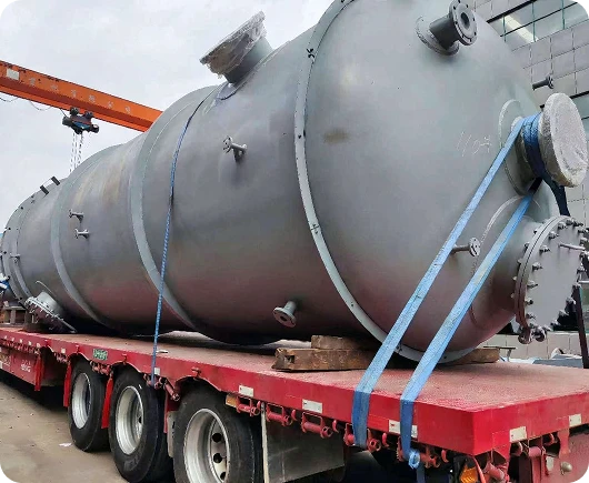
For steel vessels, the repair method depends on the defect size and depth. Common pressure vessel repair cases include:
- Local corrosion: Small areas can be repaired by weld buildup. Larger areas may require a patch repair.
- Non-through cracks: If the crack depth is below 10% of the wall thickness and no more than 1 mm, grinding may be enough. If it reaches up to 40% of the wall thickness, groove welding can be used. Deeper cracks should be treated as through-wall cracks.
- Narrow through-wall cracks: Stop holes are drilled at both ends. A V-groove is normally used when the wall is below 12 mm. An X-groove can be used for thicker walls.
- Wide cracks: The damaged section can be removed and replaced. The repair area should extend 50–100 mm beyond the crack, with a width of at least 250 mm.
These values are practical maintenance references. The final reactor vessel repair method should also follow the vessel design and applicable ASME code or project standard. ASME PCC-2 covers repair methods for in-service pressure equipment.
Cast-Iron Reactor Repair
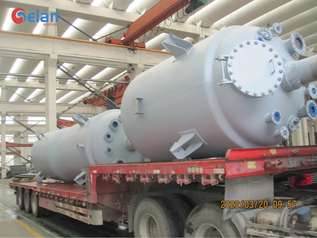
Cast-iron reactor vessels may develop sand holes, cracks, pitting, or local corrosion. These defects can often be repaired by arc welding.
For cracks, a practical reference is to drill a stop hole 3–5 mm beyond each crack end before welding. This helps prevent the crack from extending further.
Cast iron is sensitive to thermal stress during welding, so heat input and cooling should be controlled carefully.
Glass-Lined Reactor Maintenance and Repair
Glass lined reactor maintenance requires careful handling. The lining is brittle and can be damaged by impact or rapid temperature changes. Lifting should use the specified points, and welding near the lined surface should be controlled to limit heat exposure.
The repair method depends on the size and type of damage:
- Small pinholes: A corrosion-resistant metal plug can be used for local sealing.
- Larger local defects: A corrosion-resistant bolt and sealing pad can be fitted over the damaged area.
- Inorganic coating repair: Remove rust with 15–20% dilute sulfuric acid, neutralize with 10% caustic soda solution, then rinse and dry the surface. A reference coating mix by weight is 100 parts diabase powder, 5 parts sodium fluorosilicate, and 95 parts water glass.
- Organic coating repair: After the same surface preparation, a reference mix can use 100 parts epoxy resin, 15 parts dibutyl phthalate, 12–14 parts m-phenylenediamine, and 50–100 parts graphite or other filler. The repaired area is then slowly heated to 80–100°C for curing.
- Flange areas: Clamps should be evenly distributed and tightened gradually in a diagonal sequence. Uneven or excessive tightening can place local stress on the glass lining.
In practice, the key is to match the repair method to the defect size and location. Small local defects may allow glass lined reactor repair, while larger or deeper damage may require a more extensive repair or replacement decision.
Glass-Lined Reactor Spark Test
Before choosing a repair method, the damaged area should be checked carefully. Some pinholes and fine cracks are difficult to find by visual inspection alone. A glass lined reactor spark test can help locate these hidden defects and define the actual repair area.
The surface should be clean and dry before testing. Test voltage should match the lining thickness and the selected inspection method. ISO 2746 provides guidance for high-voltage testing of vitreous and porcelain enamel coatings.
Reactor Drive and Agitator Maintenance
After the vessel and lining are checked, the next focus is the drive and mixing system. Wear, misalignment, or imbalance in these parts can increase vibration and place extra load on the shaft, bearings, and seals.
V-Belt and Drive System
Check pulley alignment, belt tension, and surface wear during maintenance.
- Pulley shaft parallelism should not exceed 0.01a.
- Axial offset between the pulley center planes should not exceed 0.005a, where a is the actual center distance.
- Replace pulleys with cracks, damaged grooves, or severe wear.
- Replace belts that are aged, cracked, twisted, heavily worn, or contacting the groove bottom.
- Belts on the same pulley set should be replaced together to keep tension consistent.
Agitator Maintenance
After the drive system is checked, the agitator itself should be inspected for shaft straightness, wear, corrosion, deformation, and balance. Good agitator maintenance helps reduce vibration and protects the bearings and seals.
- Shaft straightness should be within 0.10 mm/m. At the shaft journal, the limit is 0.04 mm/m.
- If wear at the packing contact area exceeds 0.5 mm, the shaft should be rebuilt and machined back to the required size.
- Replace the agitator when uniform corrosion exceeds 30% of the original thickness.
- Local corrosion, cracks, or deformation can be repaired by welding, reshaping, or straightening when suitable.
- Paddle, frame, and anchor agitators should remain perpendicular to the shaft. The deviation should not exceed 4/1000 of blade length, with a maximum of 5 mm.
- Turbine and propeller agitators above 100 r/min should be checked for static balance. For speeds below 500 r/min, unbalance at the impeller rim should not exceed 20 g.
- When fitting the lower rolling bearing, leave about 0.5–1.0 mm axial clearance for thermal expansion.
Reactor Seal Maintenance
After the agitator is checked, the shaft sealing system should be inspected for wear, leakage, alignment, and lubrication. Both packing seals and mechanical seals depend on correct shaft condition and installation.
Packing Seal Maintenance
- For packing seals, check the gland, shaft clearance, packing arrangement, and lubrication path.
- For shaft diameters of 50–110 mm, the clearance between the gland bore and shaft should be 0.75–1.00 mm.
- The clearance between the agitator shaft and packing box should be 0.60–1.00 mm.
- The end-face gap between the gland and packing box should remain even, with a deviation within 0.3 mm.
- Packing joints should be staggered evenly around the circumference. A 30° cut can be used at each joint.
- Leave enough compression allowance during installation.
- Keep the oil ring in the correct position and make sure the lubrication passage remains open.
Mechanical Seal Maintenance
For mechanical seal maintenance, focus on shaft condition, seal-face contact, alignment, and free movement.
- Shaft-to-seal chamber perpendicularity should be about 0.05 mm.
- Seal chamber concentricity should be about 0.5 mm.
- Radial runout and axial movement should each be controlled within about 1 mm.
- The shaft surface at the seal position should have a surface roughness of at least Ra 1.6 μm.
- The seal chamber should be clean. The rotating and stationary seal faces should reach about Ra 0.2 μm and remain leak-free during a water check.
- The stationary seal face should remain perpendicular to the shaft within 0.05 mm.
- Spring direction should match the shaft rotation.
- After installation, the rotating ring should move freely. Hand rotation should feel smooth, with no sticking or abnormal resistance.
- During a tightness test, continuous bubbles indicate leakage and should be corrected before operation.
Safety Devices and Instruments
After the seal system is checked, inspect the reactor’s safety devices and instruments. Safety valves, rupture disks, and pressure gauges should follow the applicable pressure-vessel inspection requirements. API RP 576 covers inspection practices for pressure-relieving devices.
For the level gauge:
- Perform a hydrostatic test at 1.5 times its nominal pressure before installation or use.
- Repair or replace it if the inspection period has expired.
- Replace cracked or broken glass plates or tubes.
- Repair valves that are stuck or cannot operate normally.
- Investigate repeated false level readings before returning the reactor to service.
Other alarms, interlocks, and safety instruments should also be checked before startup.
Hydrostatic Test After Reactor Repair
After welded repairs, a pressure vessel hydrostatic test may be required before the reactor returns to service. Remove trapped air first, then increase the pressure slowly.
A practical testing reference includes:
- Hold the test pressure for 10–30 minutes.
- Then reduce to the maximum working pressure for inspection.
- There should be no leakage, visible deformation, or abnormal sound.
- For insulated vessels or surfaces that cannot be inspected directly, hold the maximum working pressure for at least 2 hours. Pressure should remain stable.
- If a tightness test is required, perform it after the hydrostatic test. The test gas temperature should be at least 5°C.
The final test method and pressure should follow the vessel design and applicable repair code. ASME PCC-2 includes examination and testing requirements for repaired pressure equipment.
Reassembly and Installation Checks
After testing is complete, the reactor should be reassembled and checked before startup.
- Vessel level tolerance should be within 1 mm/m.
- Installation elevation tolerance should be within ±5 mm.
- Keep at least 40 mm between the agitator and nearby dip pipes, thermowells, or heating coils.
- Flange misalignment should be below 1 mm, and the face gap should be below 2 mm.
- Flange sealing faces should be clean and free from deep scratches, corrosion, weld marks, or residue.
- Install only one gasket between mating flanges. Do not stack gaskets to correct excessive flange gaps.
- Tighten flange bolts evenly with a torque wrench in two to three passes.
- Do not mix bolts of different materials or specifications on the same flange.
- Where hot or cold tightening is required, follow the specified operating procedure.
These checks help prevent leakage, misalignment, and unnecessary load on the agitator and sealing system after maintenance.
Preventive Maintenance Checklist for Reactor
A preventive maintenance checklist for reactor helps organize routine inspection and reduce missed items before startup.
| Area | What to Check | Common Problems |
|---|---|---|
| Reactor vessel | Wall thickness, welds, deformation | Corrosion, cracks, thinning |
| Glass lining | Surface condition | Pinholes, chips, exposed metal |
| Drive system | Belts, pulleys, alignment | Wear, looseness, misalignment |
| Agitator | Shaft, blades, bearings | Wear, corrosion, imbalance |
| Packing seal | Packing, gland, lubrication | Leakage, uneven compression |
| Mechanical seal | Seal faces, shaft movement | Wear, leakage, sticking |
| Safety devices | Valves, gauges, interlocks | Failure, blockage, false readings |
| Flanges | Gaskets, bolts, sealing faces | Leakage, damage, uneven tightening |
| Pressure boundary | Vessel integrity after repair | Leakage, deformation |
FAQ About Reactor Maintenance
How Often Should a Chemical Reactor Be Inspected?
There is no fixed interval for every reactor. Chemical reactor inspection should be based on operating conditions, corrosion rate, previous inspection results, and the applicable code.
What Should a Reactor Inspection Checklist Include?
A reactor inspection checklist should cover the vessel, welds, lining, agitator, seals, safety devices, flanges, and instruments. A reactor vessel inspection should focus on corrosion, cracks, wall thinning, deformation, and previous repair areas.
What Does Reactor Preventive Maintenance Include?
Reactor preventive maintenance includes regular inspection and early correction of wear, corrosion, leakage, and misalignment. A reactor maintenance checklist should cover both the pressure vessel and its main mechanical components.
Can a Damaged Reactor Be Repaired, or Should It Be Replaced?
It depends on the damage. Small defects may allow chemical reactor repair, while severe corrosion, cracks, wall thinning, or lining damage may require replacement.
For glass-lined equipment, glass lined reactor inspection should confirm whether the damage is limited to the lining or has reached the metal substrate. Local glass lined reactor repair may be possible for smaller defects.
Gelan does not provide on-site reactor repair services. If replacement is required, we can redesign and manufacture a new reactor based on the process conditions and project requirements.
Is a Reactor Hydrostatic Test Required After Repair?
It may be required after repairs that affect the pressure boundary. A reactor hydrostatic test should follow the vessel design, repair method, and applicable code.
Conclusion
Reactor maintenance should cover more than the vessel body. The agitator, drive system, seals, safety devices, lining, and installation condition also need regular checks.
If damage can no longer be repaired safely, replacement should be considered. Gelan reactor pressure vessels can be redesigned and manufactured around the process conditions, materials, dimensions, and project requirements.