

TL;DR
- • SOFCs generate electricity and usable heat through a high-temperature electrochemical process.
- • They can use hydrogen or properly treated hydrocarbon fuels.
- • Performance depends on cell materials, fuel quality, temperature control, and heat recovery.
- • SOFCs are best suited to stable power loads and combined heat and power projects.
- • Gelan supports fuel treatment, heat recovery, controls, and skid-mounted SOFC integration.
A solid oxide fuel cell turns fuel directly into electricity and usable heat. It uses a solid ceramic electrolyte. It does not depend on combustion inside the cell. This makes SOFC a promising option for efficient and stable power generation.
However, good cell performance does not guarantee reliable field operation. As Gelan’s Overseas Sales Director, I have worked on oil, gas, petrochemical, and energy projects for over 10 years. In this guide, I explain how SOFC works, how it is built, and where its strengths and limits come from. This will help you understand the technology and evaluate an SOFC project more clearly.
CONTENT:
- What Is a Solid Oxide Fuel Cell (SOFC)?
- How Does a Solid Oxide Fuel Cell Work?
- What Are the Main Solid Oxide Fuel Cell Components and Materials?
- Solid Oxide Fuel Cell Types: Planar, Tubular, and Operating Temperature
- What Are the Advantages and Disadvantages of Solid Oxide Fuel Cells?
- FAQ About Solid Oxide Fuel Cells
- Conclusion
What Is a Solid Oxide Fuel Cell (SOFC)?
A solid oxide fuel cell is a high-temperature electrochemical power device. Its name comes from its solid ceramic oxide electrolyte. Fuel enters one side of the cell. Air enters the other side. The cell then produces electricity and usable heat without combustion inside the electrochemical core.
The easiest way to understand an SOFC is as an on-site power generator. It is not a battery. It keeps producing power while fuel and air are available. Today, solid oxide fuel cells are mainly used for stationary power. Common uses include distributed generation, combined heat and power, microgrids, data centers, and residential energy systems. These uses show the growing role of solid oxide fuel cell technology in reliable distributed energy.
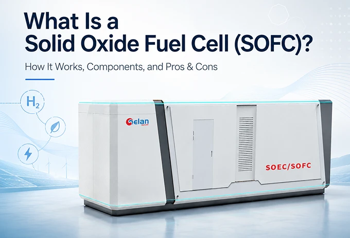
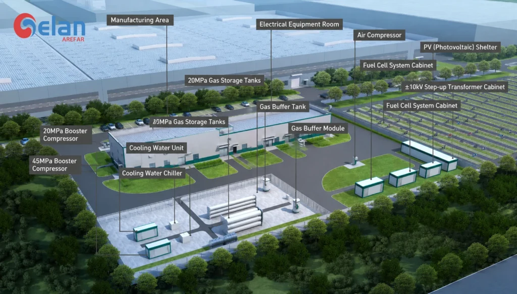
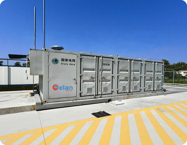
In commercial projects, Gelan has helped customers apply SOFC systems to natural-gas charging stations and pure-hydrogen distributed power. One project used three 10 kW units in a 30 kW skid-mounted hydrogen system. It supported peak shaving, critical loads, and combined heat and power. These applications rely on the same electrochemical process inside the cell. The next section explains how that process works.
How Does a Solid Oxide Fuel Cell Work?
The solid oxide fuel cell working principle is based on two controlled flows. Oxygen ions move through the ceramic electrolyte. Electrons move through the external circuit.
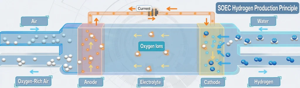
Air first enters the cathode. Oxygen gains electrons and forms oxide ions. These ions cross the electrolyte and reach the anode. Fuel then reacts with the oxide ions. This reaction releases electrons. The electrons flow through the external circuit and produce DC power. The process also generates heat and reaction products.
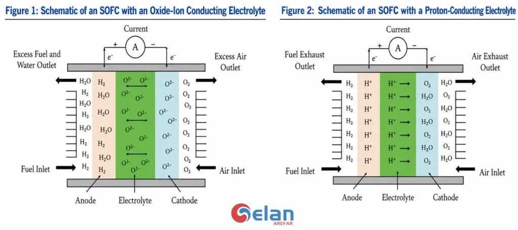
The easiest way to follow the process is to track the two paths. Ions move inside the cell. Electrons move outside the cell. The continuous movement of both creates usable electrical power.
The solid oxide fuel cell diagram below shows the process in four steps:
- Air supplies oxygen to the cathode.
- Oxide ions cross the electrolyte.
- Fuel reacts with oxide ions at the anode.
- Electrons flow through the external circuit.
Fuel and air remain on separate sides. The dense electrolyte blocks the gases. It only allows ions to pass through.
An SOFC power system can also be understood at three levels. The cell is the basic reaction unit. The stack connects many cells to increase voltage and power. The complete system adds air supply, fuel supply or reforming, heat recovery, power management, and controls. The reaction happens inside the cell. The surrounding units keep it running and deliver usable power.
Solid Oxide Fuel Cell Anode and Cathode Reactions
The electrochemical reaction is divided between two electrodes. At the cathode, oxygen from the air gains electrons and forms oxide ions. At the anode, the fuel reacts with these ions and releases electrons. The separation of these reactions forces the electrons through an external circuit. This flow produces electricity.
The main solid oxide fuel cell anode and cathode reactions are shown below:
| Reaction location | Electrochemical reaction | What happens |
|---|---|---|
| Cathode | O₂ + 4e⁻ → 2O²⁻ | Oxygen gains electrons and forms oxide ions. |
| Hydrogen anode | 2H₂ + 2O²⁻ → 2H₂O + 4e⁻ | Hydrogen reacts with oxide ions and releases electrons. |
| Overall reaction | 2H₂ + O₂ → 2H₂O + electricity + heat | Hydrogen and oxygen form water while releasing energy. |
Hydrogen is the clearest example, but it is not the only reactive fuel component. Carbon monoxide can also react at the anode:
CO + O²⁻ → CO₂ + 2e⁻
These reactions do not happen on their own. They depend on the cell structure. The cathode must allow air to reach the reaction sites. The electrolyte must carry oxide ions while keeping fuel and air separate. The anode must distribute fuel and release electrons. This is why SOFC performance depends closely on its components and material selection.
What Are the Main Solid Oxide Fuel Cell Components and Materials?
The basic solid oxide fuel cell construction has three active layers. These are a porous anode, a dense electrolyte, and a porous cathode. The pores let fuel and air reach the reaction sites. The dense electrolyte keeps both gases separate. It also carries oxide ions through the cell.
The main solid oxide fuel cell components also include interconnects and seals. Interconnects link adjacent cells and collect current. Seals prevent fuel and air from mixing inside the stack.
| Component | Main function | Common solid oxide fuel cell materials | Required structure |
|---|---|---|---|
| Anode | Oxidizes fuel and releases electrons | Ni–YSZ cermet | Porous and electrically conductive |
| Electrolyte | Carries oxide ions and separates gases | YSZ; also ScSZ or GDC | Thin, dense, and gas-tight |
| Cathode | Reduces oxygen into oxide ions | LSM or LSCF | Porous and catalytically active |
| Interconnect | Carries current between cells and guides gas flow | Ferritic stainless steel or ceramic materials | Conductive and gas-tight |
| Seal | Keeps fuel and air in separate channels | Glass or glass-ceramic | Gas-tight at operating temperature |
YSZ means yttria-stabilized zirconia. It is the most established solid oxide fuel cell electrolyte. Ni–YSZ is widely used at the anode. Nickel carries electrons and supports fuel reactions. YSZ provides an oxide-ion path. LSM is a common cathode material in traditional high-temperature cells. LSCF is often used in lower-temperature designs.
Gelan uses an anode-supported cell design in its current project platform. The supplied anode layer is NiO–YSZ. The electrolyte is YSZ. The cathode is LSM. The cell size is 15 × 15 cm. Its specified operating range is 650–800°C. The thick anode supports a much thinner electrolyte. This shortens the oxide-ion path and reduces electrical resistance.
These parts perform the same basic roles in every SOFC. However, they can be arranged in different shapes. The two main designs are planar and tubular cells. Their geometry changes sealing, current collection, heat transfer, and stack assembly.
Solid Oxide Fuel Cell Types: Planar, Tubular, and Operating Temperature
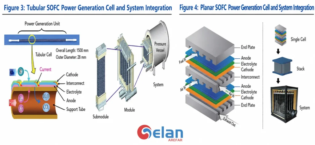
The same anode, electrolyte, and cathode can be arranged in different shapes. The two main designs are planar and tubular. Cell shape affects stack size, current flow, gas sealing, and manufacturing.
Planar vs Tubular Solid Oxide Fuel Cell Construction
Planar cells use flat ceramic layers. They create short current paths and compact stacks. This supports higher power density. However, each cell needs reliable seals between the fuel and air channels. A tubular solid oxide fuel cell forms the active layers around a tube. Some tubular designs need fewer seals. They can also tolerate repeated thermal cycling. Their longer current paths often reduce volumetric power density.
| Factor | Planar SOFC | Tubular SOFC |
|---|---|---|
| Cell shape | Flat plate | Tube |
| Stack layout | Compact layered stack | Bundled tubes |
| Current path | Shorter | Longer |
| Power density | Generally higher | Generally lower |
| Gas sealing | More demanding | Often simpler |
| Thermal cycling | More sensitive to seals and interfaces | Often more tolerant |
Operating range is another common way to describe SOFC designs. The broad solid oxide fuel cell temperature range is about 500–1,000°C. Zirconia-based cells often operate at 700–1,000°C. Ceria-based electrolytes can work at lower temperatures.
There is no single fixed boundary for each temperature class. A practical guide is shown below. The ranges may overlap between developers and material systems.
| SOFC category | Practical temperature range | Main design effect |
|---|---|---|
| High temperature solid oxide fuel cells | About 800–1,000°C | Strong ion conductivity and more usable exhaust heat |
| Intermediate temperature solid oxide fuel cells | About 600–800°C | Lower material stress with useful reaction performance |
| Low temperature solid oxide fuel cells | Around 600°C or below | Faster startup potential but higher material-performance demands |
Cell structure and operating temperature directly shape system performance. They influence efficiency, startup, heat use, installation space, and long-term operation. The next section explains the main benefits of SOFC technology and the factors that project owners should evaluate before selection.
What Are the Advantages and Disadvantages of Solid Oxide Fuel Cells?
The main solid oxide fuel cell advantages and disadvantages come from one feature: high operating temperature. It improves reaction performance and heat recovery. It also increases startup time and material stress.
| Factor | Advantage | Project Consideration |
|---|---|---|
| Electrical efficiency | SOFC systems can reach about 60% electrical efficiency | Actual output depends on fuel processing and auxiliary loads |
| Heat recovery | Total fuel use can exceed 85% in CHP applications | The project needs a useful and stable heat demand |
| Fuel flexibility | Hydrogen and prepared hydrocarbon fuels can be used | Hydrocarbon fuels may need reforming and gas cleaning |
| Solid electrolyte | No liquid electrolyte handling is required | Ceramic parts still need careful temperature control |
| Continuous operation | Well suited to stable stationary loads | Frequent cold starts are less suitable |
| High temperature | Supports fast electrochemical reactions | It creates thermal stress and longer startup times |
| Long-term durability | Few moving parts inside the cell | Electrodes, seals, and interconnects can still degrade |
| Fuel quality | Reformate can contain hydrogen and carbon monoxide | Sulfur and carbon deposition can reduce performance |
The efficiency figure needs context. DOE reports about 60% fuel-to-electricity efficiency for SOFCs. Total fuel use can exceed 85% when the exhaust heat is recovered through a suitable waste heat recovery system. This makes SOFC attractive for sites that need both steady power and useful heat.
The main solid oxide fuel cell disadvantages involve temperature and durability. Long startup times limit fast response. Repeated shutdowns can increase thermal stress. High temperatures can also accelerate corrosion and component degradation. Chromium, sulfur, and carbon deposits may damage active reaction sites.
From Gelan’s project experience, SOFC is strongest under stable operating conditions. A continuous load is important. A steady fuel supply also matters. Heat recovery can improve the project value. Frequent cold starts and large load swings require more careful review.
SOFC selection should not start with efficiency alone. Fuel composition, load profile, startup frequency, heat demand, and site conditions must also be checked. The following questions address the most common points raised during early project discussions.
FAQ About Solid Oxide Fuel Cells
What Temperature Does a Solid Oxide Fuel Cell Operate At?
Most SOFCs operate between 500°C and 1,000°C. The exact range depends on the electrolyte, electrode materials, and cell design. Gelan’s current project platform uses a specified range of 650–800°C.
Are All Solid Oxide Fuel Cells Tubular?
No. The two main designs are planar and tubular. Planar cells use flat layers and form compact stacks. Tubular cells place the active layers around a tube. This can reduce sealing complexity.
Where Are Solid Oxide Fuel Cells Used?
SOFCs are mainly used for stationary power. Typical uses include distributed generation, combined heat and power, microgrids, data centers, and utility power. Their continuous output suits sites with stable electrical and thermal loads.
Gelan has applied SOFC systems to natural-gas charging stations and pure-hydrogen distributed power. We can also assess projects with associated gas, industrial by-product gas, or a steady heat demand.
What Is the Difference Between SOFC and PEM Fuel Cells?
The main solid oxide fuel cell vs PEM difference is operating temperature. SOFCs normally operate at 500–1,000°C. PEM fuel cells operate below 120°C. PEM systems start faster and are widely used in vehicles. SOFC systems provide higher-grade heat and better suit steady stationary loads.
Why Do Solid Oxide Fuel Cells Degrade?
SOFC degradation can come from thermal stress, electrode aging, seal failure, carbon deposition, sulfur poisoning, and chromium contamination. These effects reduce active reaction areas or increase internal resistance.
Cell aging cannot be removed through system design alone. However, proper fuel treatment, reforming, preheating, and temperature control can reduce avoidable operating risks. These are key areas reviewed by Gelan during system design.
Is an SOFC Cell a Complete Power Generation System?
No. A cell is the basic electrochemical unit. Multiple cells form a stack. A complete system also needs fuel processing, air supply, thermal management, power conditioning, and controls.
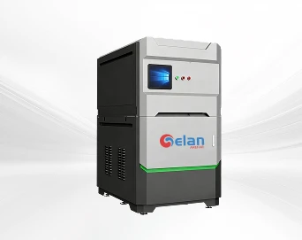
Gelan can integrate the stack with reforming, fuel and air preheating, heat recovery, power management, controls, and skid-mounted equipment.
Conclusion
A solid oxide fuel cell converts fuel into electricity and usable heat. Its performance depends on cell design, materials, fuel quality, and temperature control.
For industrial projects, the full system also matters. Gelan supports fuel treatment, heat recovery, controls, and skid integration for natural gas, hydrogen, associated gas, and by-product gas applications.