
Waste Plastic Pyrolysis Plant for Oil & Aluminum Recovery
- Feedstocks: Waste aluminum foil packaging, aluminum-plastic laminates, and waste plastics, including PE materials, PE and PVC cable sheathing, plastic bags, and PP beverage bottles.
- Feed Preparation: The batch plant can accept materials without prior removal of wire, sand, or moisture. For the continuous plant, screen out impurities larger than 5 cm before feeding.
- Outputs: Pyrolysis oil, aluminum powder from aluminum-bearing feedstocks, non-condensable combustible gas, and solid residue.
- Processing Capacity: Up to 25 t per 48-hour batch for the batch plant and 25–30 t per 24 h for the continuous plant.
- Plant Options: Batch and continuous plants.
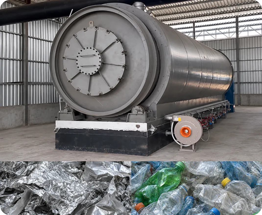
Waste Plastic Pyrolysis Plant Types
GELAN offers a batch plant for waste plastics, aluminum foil packaging, and aluminum-plastic laminates, as well as a continuous plant for suitable waste plastics.
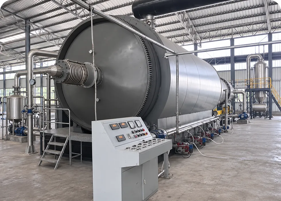
Batch Plastic Pyrolysis Plant
- Feed Preparation: Waste aluminum foil packaging,aluminum-plastic laminates, and plastics can be loaded without first removing wire, sand, or moisture.
- Feeding Method: A mechanical feeder loads the material before each batch.
- Processing Capacity: Up to 25 t per 48-hour batch.
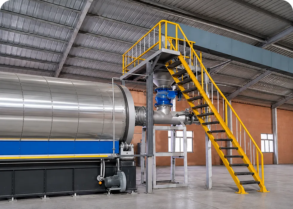
Continuous Plastic Pyrolysis Plant
- Feed Preparation: Screen out impurities larger than 5 cm before feeding.
- Feeding Method: A sealed screw feeder delivers material to the reactor during operation.
- Processing Capacity: 25–30 t per 24 h.
Waste Plastic Pyrolysis Plant Specifications
Choosing the right plastic pyrolysis plant requires a clear understanding of its processing capacity, operating parameters, and other technical specifications. For any details not listed here, please contact GELAN.
| Parameter | SH-LJ-20 | SH-LJ-18 | SH-LJ-15 | SH-LJ-30 |
|---|---|---|---|---|
| Feedstocks | Pharmaceutical aluminum-plastic panels, aluminum-plastic food bags, Tetra Pak aluminum-plastic milk cartons, aluminum-plastic panels for construction, aluminum-plastic films, waste plastic bags, pipes, plastic films, bottles, electrical insulation materials, etc. PP: Films, plastic ropes, tableware, pots, barrels, bags, caps, car bumpers, etc. PS: Electrical appliances, stationery, cups, food containers, foam products, toys, etc. ABS: Computer housings, TV housings, plastic dinnerware, etc. | |||
| Working mode | Batch | Batch | Batch | Continuous |
| Processing capacity | 20 t/day | 18 t/day | 15 t/day | 25–30 t/24 h |
| Equipment weight | 50–60 t | 50–60 t | 50–60 t | — |
| Reactor volume | 60 m³ | 55 m³ | 50 m³ | — |
| Reactor size (D × L, mm) | 3000 × 9000 | 3000 × 8000 | 2800 × 7700 | — |
| Reactor material | Q245R/Q345R | Not specified | Q245R/Q345R | — |
| Reactor wall thickness | 18/20 mm | Not specified | 18/20 mm | — |
| Reactor structure | Horizontal rotation | Horizontal rotation | Horizontal rotation | Horizontal rotation |
| Working pressure | Atmospheric pressure | Atmospheric pressure | Atmospheric pressure | Normal pressure |
| Reactor rotation speed | 1 revolution per 2.5 min | 1 revolution per 2.5 min | 1 revolution per 2.5 min | — |
| Power | 11 kW | 11 kW | 7.5 kW | 30 kW/H while running (as stated). Average operation: 20 h/day. |
| Electrical supply | — | — | — | 380 V, 50 Hz |
| Control system | Control panel / PLC | Control panel / PLC | Control panel / PLC | Control panel / PLC |
| Cooling method | Circulating water cooling | Circulating water cooling | Circulating water cooling | Water cooling |
| Circulating water flow | 30 t/h | 30 t/h | 30 t/h | — |
| Water consumption | 9 T/N | Not specified | 9 T/N | 3 t/24 h |
| Heating method | — | — | — | Direct heating |
| Heating fuel | Fuel oil | Fuel oil | Fuel oil | Oil, natural gas |
| Fuel consumption | 200–300 kg fuel oil | 200–260 kg fuel oil | 200–260 kg fuel oil | Not specified |
| Reactor drive type | External gear | External gear | External gear | Gear |
| Installation | Foundation | Foundation | Foundation | Foundation |
| Noise (dB(A)) | ≤ 80 | ≤ 80 | ≤ 80 | ≤ 85 |
| Feeding method | Mechanical feeding | Mechanical feeding | Mechanical feeding | Automatic feeding |
| Discharge method | Side discharge | Side discharge | Side discharge | — |
| Operating platform | Steel structure | Steel structure | Steel structure | Steel structure |
| Labour | 2–3 workers per unit | 2–3 workers per unit | 2–3 workers per unit | 3 shifts, 6 people in total |
*The table provides selected data for reference. Please contact GELAN directly for detailed specifications or information on items not listed here.*
Outputs and Uses of Waste Plastic Pyrolysis
Depending on the feedstock, GELAN’s pyrolysis plant for waste plastics, aluminum foil, and aluminum-plastic materials can produce pyrolysis oil, aluminum powder, and non-condensable combustible gas. Each output has its own uses.
Can fuel compatible industrial boilers and furnaces or be distilled into fractions for further refining.
Pyrolysis Oil
Can be sent to aluminum recyclers for further processing into recycled aluminum.
Aluminum Powder
Can be routed back to the furnace to heat the reactor and reduce the need for external fuel.
Combustible Gas
Why Choose a GELAN Waste Plastic Pyrolysis Plant?
GELAN’s waste plastic pyrolysis plants speed up loading and residue discharge, simplify maintenance, and reuse process gas to cut fuel demand. Built-in safeguards protect operators, while flue gas treatment reduces dust and sulfur emissions.
Faster Loading and Residue Discharge
- Batch Plant: The mechanical feeder loads 25 tonnes in 50 minutes, and the side-discharge system removes solid residue in 40 minutes.
- Continuous Plant: The sealed screw feeder handles 15 tonnes in 50 minutes, and the rear discharge system removes solid residue in 100 minutes.
More Even Heating for Faster Pyrolysis
The horizontal reactor rotates through 360° to heat the reactor body more evenly. This helps the feedstock break down faster and reduces uneven heating that can shorten reactor life.
Lower Fuel Demand Through Gas Reuse
The plant burns non-condensable pyrolysis gas to supply process heat, reducing the need for external fuel. The equipment brochure reports fuel savings of up to 80%.
Easier Maintenance and Less Pipeline Buildup
The box-type condenser is easy to access for inspection and maintenance. A separation system captures heavy components in the vapor stream, and sloped piping helps reduce oil buildup.
Built-In Safeguards and Flue Gas Treatment
Pressure and temperature alarms, an emergency stop, and active and passive explosion relief help protect operators. A wet scrubber removes over 95% of flue gas dust, while chemical desulfurization reduces sulfur compounds in the exhaust.
FAQs About Waste Plastic to Fuel Oil Pyrolysis Plant
Q1. What does the 7.5 or 11 kW rating refer to on the batch models?
It refers to the main reactor drive power. The SH-LJ-15 uses a 7.5 kW reactor drive, while the SH-LJ-18 and SH-LJ-20 use 11 kW drives. Total plant power requirements also include auxiliary equipment.
Q2. At what stage is the oil collected as a liquid?
The oil becomes liquid in the condenser, where cooling water removes heat from the pyrolysis vapors. The liquid oil is then collected after passing through the downstream oil–gas separator.
Q3. How does the batch plant separate the condensed oil from the remaining gas?
The mixture leaving the condenser enters an oil–gas separator. The liquid oil goes to the oil outlet, while the remaining non-condensable gas passes through a water seal tank and returns to the heating furnace for use as fuel.
Q4. What happens to non-condensable gas when there is more than the heating furnace needs?
Excess non-condensable gas is routed to a separate gas storage vessel.
Q5. What happens to solid residue on the continuous line between reactor discharge and packaging?
The residue passes through a switching valve and a transfer unit before entering a nitrogen-fed cooling bin. Once cooled, the residue is sent for packaging.
Individual Equipment for Your Plastic to Fuel Oil Pyrolysis Plant
GELAN supplies standalone condensers, oil–gas separators, and oil storage tanks for new or existing plastic pyrolysis plants. Each unit can be ordered separately.
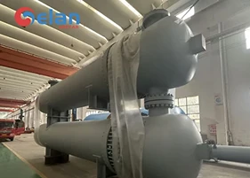
Shell & Tube Heat Exchanger
Serves as a pyrolysis vapour condenser, cooling the vapours from the reactor to recover liquid pyrolysis oil.
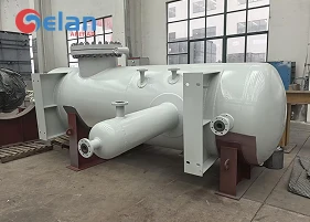
Separator Vessel
The oil–gas separator directs condensed oil to storage and routes non-condensable gas to the furnace for reuse as fuel.
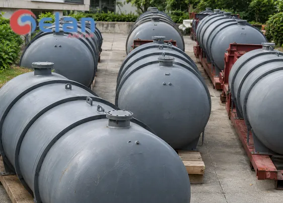
Storage Tank
Recovered oil is held in a pyrolysis oil storage tank until it is shipped or transferred to a refining unit.
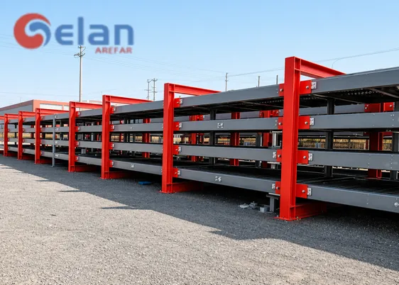
Structural Steel
Forms the operating platform for the continuous pyrolysis plant, giving operators access to equipment above ground level.
More Pyrolysis and Oil Distillation Solutions from GELAN
In addition to waste plastic pyrolysis plants, GELAN supplies systems for processing waste tyres, rubber, and oil sludge, as well as vacuum distillation units for further processing pyrolysis oil.
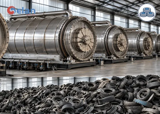
Tyre Pyrolysis plant
Turns waste tyres and rubber into pyrolysis oil, carbon black, and combustible gas. Steel-reinforced tyres also yield recoverable steel wire.
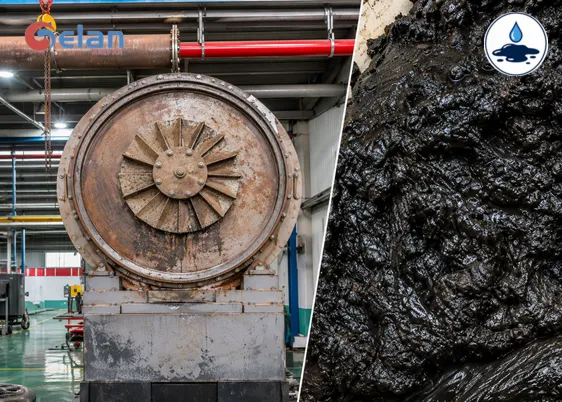
Oil Sludge Pyrolysis Plant
Recovers heavy oil from sludge generated during oil extraction, transport, refining, and storage. Additional outputs include combustible gas and treated solids.
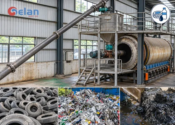
Continuous Pyrolysis Plant
Designed for projects that need to recover oil as feedstock is supplied during operation. Configurations are available for tyres and rubber, suitable plastics, or oil sludge.
Vacuum Distillation Unit (VDU)
Separates pyrolysis oil into fractions under reduced pressure, allowing higher-boiling components to distill at lower temperatures.
Get Pricing for Your Waste Plastic Pyrolysis Plant
Working with plastic film, rigid scrap, or aluminium–plastic composites? Send GELAN a few photos of your material and your target daily throughput. We’ll outline the equipment needed for your feedstock and provide a quote.